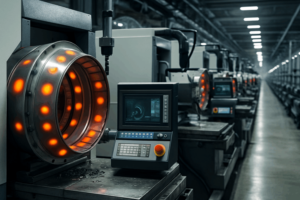
A recent performance evaluation was conducted on the Robodrill FANUC 31i, fitted with the Dapatech iTEC system via our intelligent Mini Box Compensation.
The Robodrill FANUC 31i is widely regarded as a high-precision machine. Test results demonstrated that integration with the iTEC system delivered a measurable improvement in both performance and accuracy. These enhancements are expected to be even more significant when applied to larger machine platforms.
Thermal compensation begins by identifying both generic and non-generic heat sources within a machine tool. These may include internal components, ambient environmental changes, or even operational load variations. Dapatech Systems evaluates these influences to understand how they affect precision, geometry, and tool performance.

Using real-time active sensors, temperature changes across the machine are constantly monitored. These sensors feed data directly into the compensation system, detecting and reacting to shifts in heat that would otherwise distort accuracy. This allows for immediate adjustments, no matter where in the machine the temperature variation occurs.
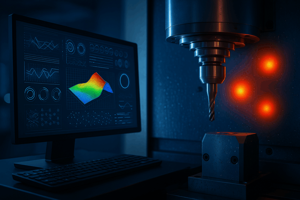
Integrated Compensation Through Advanced Algorithms After calibration, Dapatech Systems maintains accuracy across the full machine range—automatically adjusting for temperature differences in real time. Our iTEC and GTEC systems, developed with the University of Huddersfield, reduce geometric errors by up to 97% and thermal errors by 75%, supporting both 3-axis and 5-axis machines.


Three-axis machine tools exhibit a total of 21 geometric errors, while five-axis machines demonstrate 31. Each of these errors has a direct impact on both machine tool accuracy and the resulting workpiece precision.
Key contributors to these inaccuracies include axis squareness (with errors increasing proportionally to machine size), linear deviation on primary axes, and angular deviations such as roll, pitch, and yaw across all axes.
Among these, thermal variation poses the most significant challenge to maintaining consistent part quality and manufacturing precision. Fluctuations in temperature affect both the machine and the workpiece, compromising dimensional accuracy.
The GTEC (Geometric and Thermal Error Compensation) system addresses this challenge by applying a single advanced algorithm that compensates for all 31 geometric (volumetric) errors while simultaneously incorporating real-time thermal compensation. This dual correction mitigates the effects of both rigid body thermals (affecting travel distances along axes) and non-rigid body thermals (altering the machine’s structure and geometry), which can otherwise invalidate geometric calibrations.
GTEC remains the only software capable of delivering accurate compensation across the entire working volume for both geometric and thermal deviations, in real time, using a unified algorithm. System functionality can be verified easily by toggling the correction algorithm on or off.
DAPATECH systems offer real-time position-dependent compensation for geometric and thermal errors in machine tools. Their GTEC technology continuously monitors the tool’s position, allowing for immediate adjustments to ensure accuracy. Every micron resolution, a compensation is applied in real time. This dynamic approach enhances machining precision by correcting errors based on real-time data, significantly improving overall performance and reducing cumulative inaccuracies.
The iTEC (Intelligent Thermal Error Compensation) system offers an alternative solution, either fully integrated within the machine tool controller or via a secure plug-and-play interface. It provides seamless and reliable thermal error compensation without disrupting normal operations.

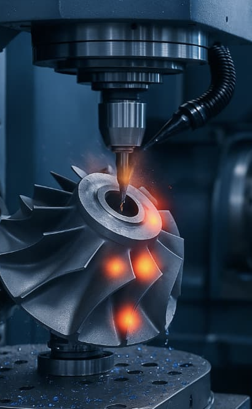
Developed in collaboration with the University of Huddersfield (UK), the GTEC system is an advanced solution designed to compensate for all geometric (volumetric) and thermal error sources that impact positioning accuracy across the entire working volume of a machine tool. It delivers full 5-axis integrated compensation via a single algorithm, accounting for all 31 known error sources. Any remaining errors are either duplicates or are non-compensable—such as spindle run-out.
Key features include:
The iTEC system offers comprehensive thermal error compensation across the entire working volume of the machine tool. It applies full 5-axis integrated compensation using a single algorithm, ensuring consistent accuracy even under variable thermal conditions.
Any machine tool capable of manufacturing with greater precision will benefit from improved final assembly efficiency and reliability. GTEC and iTEC systems are essential for applications where dimensional accuracy, thermal stability, and repeatability are critical.
Example 1: Green Energy
Accurate production of gearboxes and gears for wind turbines enables:
Example 2: Automotive Efficiency
Improved body panel accuracy allows:
Example 3: Aerospace
High-precision tooling supports:
Additional benefits apply to:
Further advantages include:
To deliver optimal accuracy, the machine tool must first undergo high-standard volumetric calibration across its entire working volume. This ensures the machine’s baseline capability exceeds the required tolerance of the components it produces:
Machine tool accuracy > Component tolerance
→ The machine can reliably produce parts within specification.
Stage 1: Geometric Compensation (GTEC)
Compensation is applied for all volumetric geometric errors:
Stage 2: Thermal Compensation (GTEC & iTEC)
Thermal effects on machine structure significantly influence accuracy:
By combining geometric and thermal correction into a single streamlined algorithm, Dapatech’s GTEC and iTEC systems provide a uniquely powerful platform for manufacturers demanding the highest levels of performance and reliability.
Advantages of the iTEC & GTEC Systems
Performance improvements resulting from the iTEC and GTEC systems are measured using Dapatech’s proprietary ESP (Error Simulation Package). This software applies the same geometric (volumetric) algorithms as the GTEC system to evaluate a machine’s positioning accuracy in real time across its entire working volume, based on precision-dependent thresholds.
In most installations, GTEC is applied to machines that have already been enhanced mechanically—either by original design or through refurbishment—up to the point of diminishing economic return. GTEC’s real advantage is in its ability to extract additional accuracy where mechanical improvements are no longer feasible.
The benefits are particularly significant on machines with large travel ranges (or “strokes”), where angular errors introduce greater inaccuracies due to increased lever arms. On such machines, even small angular deviations can result in considerable tool point errors.
Both the iTEC and GTEC systems address thermal errors effectively by responding to temperature fluctuations in the environment, machine body, and even the workpiece itself. Unlike compensation approaches that rely on static temperature points and interpolate between them, the GTEC system applies real-time thermal compensation continuously and adaptively, layered on top of the geometric (volumetric) correction.
This approach—real-time integration of thermal correction atop full volumetric compensation—is unique to the GTEC system and sets it apart from conventional compensation methodologies.
Accurate geometric (volumetric) head error compensation is essential to achieving true tool point precision across the full 5-axis machine volume. To maintain positioning integrity, these corrections must be applied in conjunction with 3-axis tool point compensation and performed seamlessly and continuously throughout the machine’s range of motion.
If head error compensation is applied independently from the 3-axis geometric corrections, this disconnect can lead to amplified errors in some areas of the machine—resulting in worse tool point accuracy than if no compensation had been applied.
The GTEC system avoids this by integrating head error compensation directly with 3-axis tool point corrections, recalculating both simultaneously in real time. This ensures that head movements do not introduce new inaccuracies and that the tool tip remains precisely positioned throughout complex multi-axis operations.
It’s important to recognise that a machine with inherent mechanical imperfections can only be made accurate by correcting for those imperfections at the tool point—not at each mechanical axis in isolation. Therefore, head error compensation must never be treated as a standalone correction layer. Systems that attempt to apply head compensation independently of 3-axis geometry risk compounding errors rather than resolving them.
Only a unified compensation algorithm—like that used in GTEC—can maintain optimal tool point accuracy across all axes, including head orientation, delivering true 5-axis compensation integrity.
Various versions of the DAPATECH compensation systems have been successfully implemented with many industrial leaders including BAE systems, GKN Aerospace, Micro Metalsmiths and Rolls Royce.
Uncompensated the error is 16.4μm and exhibits a profile influenced by the guideway pinning. With compensation the error is reduced to 0.6μm.
The results displayed below show the maximum level of compensation we have achieved so far.


The straightness error has a total range of 17.4μm before compensation & an impressive 0.8μm after.
Compensation is more difficult than for linear because it requires a stationary axis to overcome inertia.
This performance can only be achieved if the compensating axis has sufficiently good electrical and mechanical control.
The results displayed below show the maximum level of compensation we have achieved so far.


Random duty cycle spindle heating test
Position independent thermal errors in Y-axis direction reduced from 71μm to 7.5μm (≈90%)
Z Axis error reduced from 14μm to 3.5μm (≈75%)
The results displayed below show the maximum level of compensation we have achieved so far.


Average = 73% reduction for ISO type measurements on a variety of machines
The results displayed below show the maximum level of compensation we have achieved so far.
Units in Microns


All 3 pieces were machined in similar environmental conditions 25ºC. The thermal effect is quite clear and the compensation was very successful.
Average feature improvement on test dominated by high workshop temperature:
With Geometric (volumetric) Compensation = 40%
With Geometric (volumetric) and Thermal Compensation = 92%
Professor Andrew Peter Longstaff,
Huddersfield University
For more information about Dapatech’s precision thermal and geometric error compensation systems, or to discuss how our technology can improve your manufacturing accuracy, please get in touch.
Whether you’re seeking system integration advice, technical support, or want to schedule a consultation, our team is here to assist. We work closely with defence, aerospace, energy, and advanced manufacturing clients globally.
Complete the form below or contact us directly, and a Dapatech representative will respond promptly. Let us help you achieve higher performance, reduced error margins, and long-term reliability in your machining operations.
